ST SensorTile.box
Flashing SensorTile.box Firmware
Data Collection Firmware
In the links below you can find the firmware for flashing a SensorTile.box device with data collection firmware for use with the SensiML Data Studio.
Sensors |
Protocol |
Download |
Version |
|---|---|---|---|
Accelerometer/Gyroscope (6667, 3333, 1666, 833, 416, 208, 104, 52, 26 Hz), Audio (16 Khz) |
MQTT-SN |
Note
Data Collection Firmware is required to record data with the Data Studio. Data collection firmware uses large portions of RAM to enable SD card collection, and is disabled when running a Knowledge Pack.
Configuring your ST-Link V2 for the first time
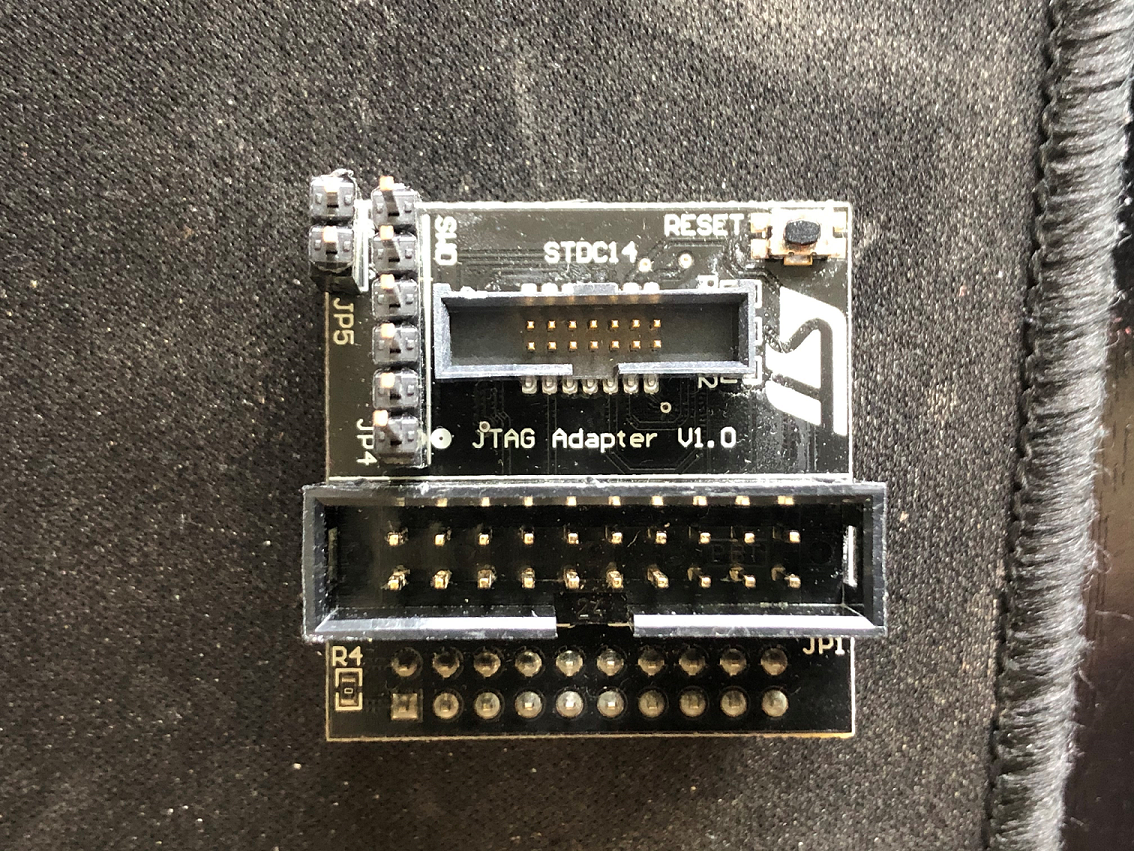
Obtain ST-LINK V2 debugger. If your SensorTile.box did not come with a 20-pin to 14-pin adapter, you will need to also need an adapter board from the ST-Link V3 (shown in pictures for this document).
Note: The ST-Link V3 does not work with the SensorTile.box currently. It does not support low-voltage (1.8V) devices.
Download and install STM32 Cube Programmer from STMicro for flashing
ST-Link V2 Setup With SensorTile.box
Ensure you have either a 20-pin to 14-pin adapter, or the adapter board from a ST-Link V3.
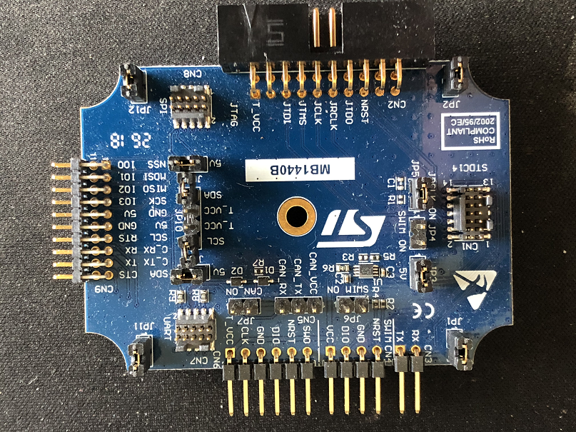
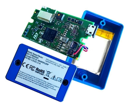
Connect the 14-pin cable to the SensorTile.box
Pin 1 is located to the OUTSIDE of the board
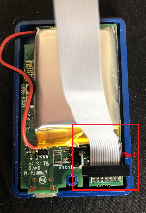
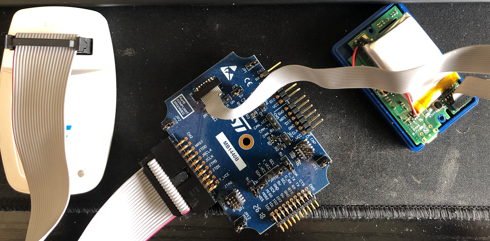
Connect the other end of the 14-pin cable to either ST-Link adapter board, and the adapter board to the 20-pin cable from the ST-Link V2. These cables are keyed, and only go in one way.
Flashing SensorTile.box With STM32 Cube Programmer
Important
Ensure your device is powered on before you begin
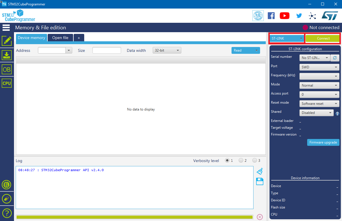
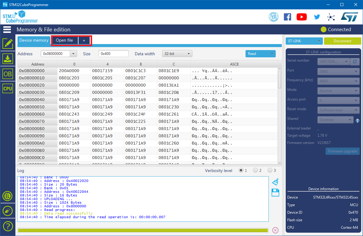
Ensure your device is connected to the ST-Link and powered on. Open STM32 Cube Programmer
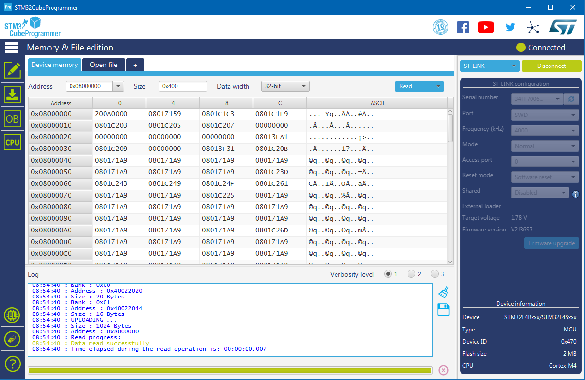
Ensure ST-Link is selected, then click on the connect button.
Once connected, you should see some of the memory dump of the chip:
Click on Open File:
Select the binary you wish to flash. Now click on Download
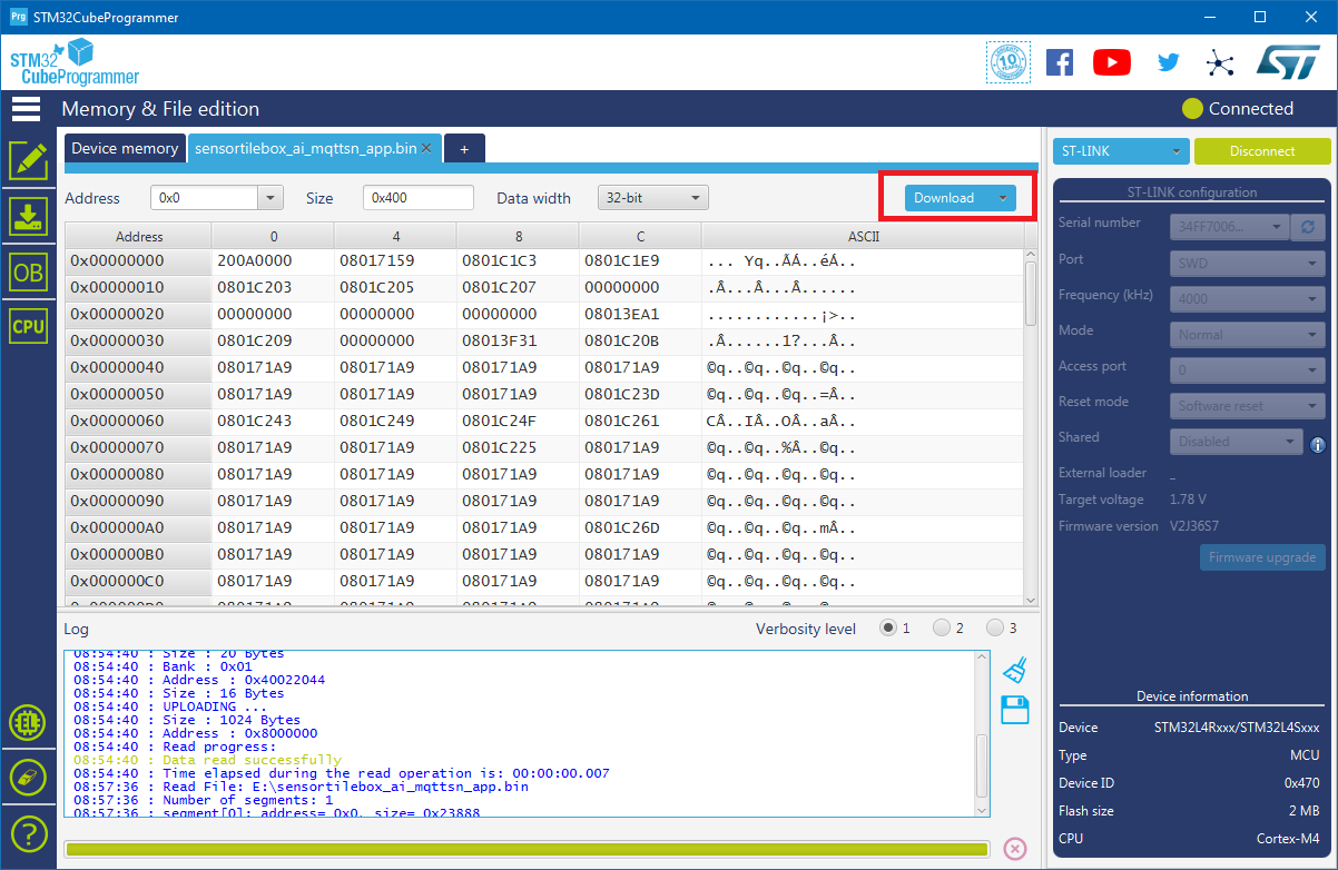
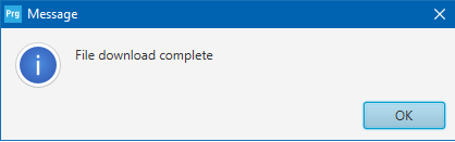
You will see text pop up in the Log on the bottom of the screen. Once the download completes, a popup will notify you.